Outlook and Summary
Outlook: Testbench
- VHDL code for top level
- No interface signals
- Instantiation of design
- Statement for stimuli generation
- Simple testbenches: response analysis by waveform inspection
- Sophisticated testbenches may need >50% of complete project resources
Notes
The most commonly used method to verify a design is simulation. As VHDL was developed for the simulation of digital hardware in the first place, this is well supported by the language.
A new top level, usually called testbench, is created which instantiates Design Under Test (DUT) and models its environment. Therefore, the entity of this top level has no interface signals. The architecture will also contain some processes or submodules which generate the stimuli for the DUT and sometimes additional processes or submodules which simplify the analysis of the responses of the DUT.
The effort which is invested into the creation of a testbench varies considerably and can cost the same amount of the time as the modelling of the DUT. It depends on the type of testbench, i.e. how much functionality (stimuli generation, response analysis, file I/O, etc.) has to be supplied.
Simple Testbench Example
entity ADDER is
  port(A, B       : in  bit;
       CARRY, SUM : out bit);
end ADDER;


architecture RTL of ADDER is
begin
  ADD : process (A, B)
  begin
    SUM   <= A xor B;
    CARRY <= A and B;
  end process ADD;
end RTL;
entity TB_ADDER is
end TB_ADDER;

architecture TEST of TB_ADDER is
  component ADDER
    port(A, B       : in  bit;
         CARRY, SUM : out bit);
  end component;
  signal A_I, B_I, CARRY_I, SUM_I : bit;
begin

  DUT : ADDER port map(A_I, B_I, CARRY_I, SUM_I);

  STIMULUS : process
  begin
    A_I <= '1'; B_I <= '0';
    wait for 10 ns;
    A_I <= '1'; B_I <= '1';
    wait for 10 ns;
    -- and so on ...
  end process STIMULUS;
end TEST;

configuration CFG_TB_ADDER of TB_ADDER is
  for TEST
  end for;
end CFG_TB_ADDER;
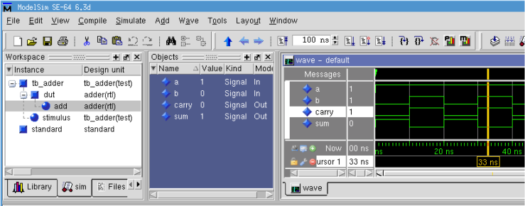
- resulting waveform in simulator (ModelSim):

Notes
The example shows the VHDL code for a simple design and its corresponding testbench. The design to be tested is the ADDER which implements a halfadder. The architecture RTL contains one pure combinational process which calculates the results for the SUM and CARRY signals whenever the input signals A or B change.
The testbench is shown on the right side. First the empty entity TB_ADDER is defined. There is no need for an interface, so no port list is present. In the architecture TEST of the testbench the component ADDER and the intermediate signals are declared. The intermediate signals (*_I) are connected to the component in the port map of the component instantiation. The signals that are connected to the input ports of the component ADDER get their values assigned in the process STIMULUS. New values are set every 10 ns. The reaction of the DUT can be observed in a waveform display of the simulator.
At the bottom of the VHDL source code, the configuration is listed. Only the architecture TEST for the TB_ADDER entity is specified and the rest is left to the default rules as the name of the component and the entity are identical.
Summary
- VHDL is a very precise language
- Signal types and directions have to match
- All objects have to be declared
- One language for design and validation
- Validation by means of a TESTBENCH
- Provides stimuli and expected response
- Top hierarchy level
- No in-/output ports
Notes
VHDL is a very strict language in which hardly a cryptic programming style is possible (as it is the case with the programming language C). Every signal, for example, has to possess a certain data type, it has to be declared at a certain position, and it only accepts assignments from the same data type.
To make a functional test of a VHDL model, a testbench can be written also in VHDL, which delivers the verification environment for the model. In it, stimuli are described as input signals for the model, and furthermore the expected model responses can be checked. The testbench appears as the top hierarchy level, and therefore has neither input- nor output ports.
Chapters of System Design > VHDL Language and Syntax > VHDL Structural Elements