State Processes
One "State" Process
FSM_FF: process (CLK, RESET)
begin
  if RESET = ’1’ then
    STATE <= START;
  elsif CLK’event and CLK = ’1’ then
    case STATE is
     when START => if X = GO_MID then
                      STATE <= MIDDLE;
                   end if;
     when MIDDLE => if X = GO_STOP then
                      STATE <= STOP;
                    end if;
     when STOP => if X = GO_START then
                      STATE <= START;
                    end if;
     when others => STATE <= START;
   end case;
  end if;
end process FSM_FF;
Notes
Three different notations of a simple state machine are shown in the picture.
The graphic on the top depicts the automaton as an abstract block diagram which contains only the relevant blocks and signals of interest.
The first block (oval) represents the logic of the automaton and the second block (rectangle) the storing elements. In the bottom graphic, the automaton is described by a so called bubble diagram.
The circles mark the different states of the automaton. If the condition connected to the corresponding transition (arrow) evaluates to ’true’ at the time the active clock edge occurs, the automaton will change its state. This is a synchronous behavior.
Here the asynchronous reset is the only exception to this behavior. At the time the reset signal gets active, the automat changes to the reset state START immediately.
In the VHDL source code the automaton is described in one clocked process. The first IF branch contains the reset sequence. In the second branch, the ELSE branch, the rest of the automaton is described. In the CASE statement which models the state transitions, the current state of the automaton is detected and it is examined whether input values are present that lead to a change of the state.
Two "State" Processes
FSM_FF: process (CLK, RESET)
begin
  if RESET = ’1’ then
    STATE <= START;
  elsif CLK = ’1’ and CLK’event then
    STATE <= NEXT_STATE;
  end if;
end process FSM_FF;

FSM_LOGIC: process (STATE, X)
begin
   NEXT_STATE <= STATE;
   case STATE is
     when START => if X=GO_MID then
                 NEXT_STATE <= MIDDLE;
                   end if;
     when MIDDLE => ...
     when others => NEXT_STATE <= START;
  end case;
end process FSM_LOGIC;
Notes
Now, the same automaton is used to show an implementation based on two VHDL processes.
The signal NEXT_STATE is examined explicitly this time.
It is inserted in the block diagram between the logic and the storing elements. In the bubble diagram no changes have to be made at this point, as the behavior remains the same.
The VHDL source code contains two processes.
The logic for the NEXT_STATE calculation is described in a separate process.
The result is a clocked process describing the storing elements and another purely combinational process describing the logic.
In the CASE statement, again, the current state is checked and the input values are examined. If the state has to change, then NEXT_STATE and STATE will differ. With the next occurrence of the active clock edge, this new state will be taken over as the current state.
How Many Processes?
- Mealy Example, unregistered Outputs
- Output logic always in an own process or concurrent assignments!
- State register inference always in an clocked (STATE) process!
- Next state logic in an own process OR in the clocked process.
- Structure and Readability
- Asynchronous combinatoric ≠ synchronous storing elements ⇒ 2 processes
- FSM states change with special input changes ⇒ 1 process more comprehensible
- Graphical FSM (without output equations) resembles one state process ⇒ 1 process
- Simulation
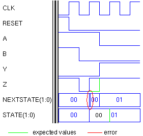
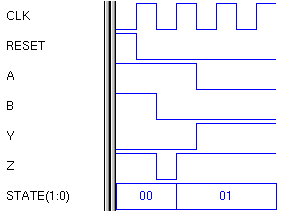
- Error detection easier with two state processes ⇒ 2 processes
| Two State Processes error easier to detect  | One State Process error difficult to detect in a big FSM or big waveform  |
- Synthesis
- 2 state processes can lead to smaller generic net list and therefore to better synthesis results ⇒ 2 processes
- Mealy Example:
- Two State Processes
- two FlipFlops for state;
- two selectors (multiplexer) for the outputs Y and Z;
- one selector for nextstate.
- ⇒ 2 D-FlipFlops
- One State Process
- two FlipFlops for state;
- two selectors (multiplexer) for the outputs Y and Z;
- two selectors for state (“nextstate” logic AND FlipFlop control logic).
- ⇒ 2 JK-FlipFlops, because of the control logic connected to the FlipFlops.
Notes
Automaton descriptions with either one or two separated processes were shown previously. Depending on the own liking and experiences, either one of the two versions is preferred by desingers. Generally there are different advantages and disadvantages:
- Structure and readability: The VHDL model should represent in a way the hardware which has to be created out of the VHDL source code. So the structure should be mirrored in the VHDL code. As purely combinational logic and storing elements are two different structural elements, these should be separated, i.e. the VHDL source code should be split into two processes. But one is normally interested in the actual changes of the states of the automaton, only. These changes can then be observed from the outside of the module. The one process description is more adequate for this view. Additionally, the graphical description, which is often used as a specification for the VHDL model, resembles more a one process than a two process description.
- Simulation: It will be easier to detect possible errors of the VHDL model in the waveform if one has access to the intermediate signal NEXT_STATE. So the time and location where the error occurs for the first time can be determined exactly and with that the source of the error. The two process version is therefore the better version.
- Synthesis: The synthesis algorithms are based on heuristics. Therefore it is impossible to give universally valid statements. But several synthesis tools tend to produce better results (no sophisticated synthesis script assumed), in the meaning of less gate equivalents, when two processes are used to describe the automaton because they are closer related to the hardware structure.
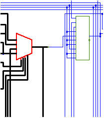
Two State Processes - Generic Netlist
- Nextstate process builds an extra logic block, terminated with one selector element (red).
- Storing elements (green) only feed with:
- Data (nextstate)
- Clock
- Constants (`0`, `1`)
- Storing elements are mapped to D-FlipFlops

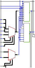
One State Process - Generic Netlist
- State process builds block with storing elements and “nextstate” logic, terminated with two selector elements (red).
- Storing elements (green) feed with:
- Clock
- Constants (`0`, `1`)
- State data
- Input data
- Storing elements are mapped to JK-FlipFlops (bigger than D-FlipFlops)

Chapters of System Design > Synthesis > Finite State Machines and VHDL