Registered Output
Modelling Aspects
- Medvedev is too inflexible
- Moore is preferred because of safe operation
- Mealy more flexible, but danger of
- Spikes
- Unnecessary long paths (maximum clock period)
- Combinational feed back loops
Notes
There are different reasons for a designer to use one or another version of the three different automatons.
The advantage of the Medvedev automaton is the reduced hardware amount needed. As the output values are identical with the state vector, no additional combinational logic is needed and the values of the output vector are changed together with the active clock edge.
But the designer has to select the code for the state vector by himself. This means that the designer has to put more effort into the design and a complete redesign is necessary if the code for the state machine has to be changed.
The Moore automaton is frequently used because this type of automaton is more flexible than the Medvedev automaton and the output calculation still depends on the state vector, only.
By this pure dependence on the state vector, the output values are calculated in a relatively safe manner, which means, the new values are stable long before the next active clock edge occurs and spikes are avoided.
A disadvantage which becomes sometimes relevant is that a change of the input vector needs one complete clock cycle to affect the output vector (first, the state vector has to change before the output vector can change). Sometimes, this delay of time is unacceptable and consequently the Moore automaton can not be used.
The Mealy automaton is the most flexible of the automatons presented. As the output vector depends on the state vector and the input vector, it can react on every change of a value. But there are also some disadvantages, like the occurrence of spikes as shown before.
If two Mealy automatons are connected in a row, there is the danger of combinational feedback loops, as demonstrated in the picture above. Additionally, long paths are created: Two logic blocks are connected in a row, so a change of a value needs a relatively long time to propagate through the logic to the next flip flops. Hence, the clocking frequency is severely limited.
Fundamentals
- Avoiding long paths and uncertain timing
- With one additional clock period
- Without additional clock period (Mealy)
Notes
Combinational feedback loops can be avoided if the outputs are “clocked”, i.e. if the outputs are connected to flip flops.
Generally, clocked outputs are used to break up combinational loops and long paths. Thus, they assure a safe timing behavior.
By clocking all outputs, the output logic is separated from the next logic block of the subsequent module and by this, the path through logic elements is shortened and higher clock frequencies are possible.
Furthermore, synthesis tools often have problems when optimizing logic paths which pass module boundaries for speed. By clocking the outputs, these problems can be avoided.
Another advantage is that the successive module can work with “safe” input data. Safe means that the data changes with the active clock edge, only, and thus spikes are ruled out.
This allows the designer of the successive module more design flexibility. Two versions are known for clocking the output.
In the first version, flip flops are inserted between the output logic and the state machine outputs which leads to an additional delay of one clock period. However, this delay, sometimes, can not be accepted.
In the second version, Flip Flops are present at the state machine output and the output logic uses the NEXT_STATE signal in addition to the state vector.
For bigger state machines, this can lead to incomprehensible dependencies and relatively long paths as two logic blocks are connected in a row, again. But this version of a state machine is the most flexible and the fastest (in terms of latency) which provides safe (clocked) output signals.
Registered Output Example (1)
architecture RTL of REG_TEST is
  signal Y_I, Z_I  : std_ulogic;
  signal STATE     : STATE_TYPE;
  signal NEXTSTATE : STATE_TYPE;
begin

REG: • • • -- clocked STATE process
CMB: • • • -- Like before

-- concurrent signal assignments
-- for output
Y_I <= ’1’ when
   (STATE=MIDDLE and (A or B)=’0’) or
   (STATE=STOP and (A and B)=’0’) else
   ’0’;
Z_I <= ’1’ when
   (STATE=START and (A and B)=’1’) or
   (STATE=MIDDLE) or
   (STATE=STOP and (A or B)=’1’) else
   ’0’;
 OUTPUT: process(CLK, RESET)
 begin
   if RESET = '1' then
     Y <= '0'; Z <= '0';
   elsif CLK’event and CLK=’1’ then
     Y <= Y_I;
     Z <= Z_I;
   end if ;
 end process OUTPUT;
end RTL;
Notes
In the picture, the example of the Mealy automat is shown again.
In the bubble diagram, the assignments which were hidden behind the states before are now explicitly connected to self loops.
Furthermore, the transitions between states also have signal assignments for the output signals.
As transitions take place only when an active clock edge occurs, it is clear that a value is assigned to the output signals with every active clock edge, i.e. flip flops have to be provided for the outputs.
As the signal assignments of the old state (which will be exited) are connected to the transitions, the output values depend only on the current (old) state (STATE) but not on the new state (NEXT_STATE).
Generally, the signal assignments can be hidden again behind the states in the graphical diagram. For this, so called in-state actions for the self loops and exit-actions for the transitions are used.
In the VHDL source code, intermediate signals (Y_I, Z_I) are evaluated. The values of these signals depend on the input values and the current state. In the following clocked process, the intermediate signals are connected to flip flops.
Waveform Registered Output Example (1)

- One clock period delay between STATE and output changes.
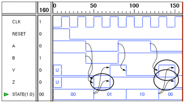
- Input changes with clock edge result in an output change. (Circles = Danger of unmeant values)
Notes
The waveform depicts the simulation results of the clocked Mealy automaton.
It can be sees clearly that the output values change one clock period after the change of the state vector.
Furthermore, it can be seen that changes of the input values affect the output values just when the next active clock edge occurs.
All value changes of intermediate signals occur only synchronously to the clock so that the state machine has a fixed and well known behavior. Still, the modelling has to be carried out carefully. It is essential to consider the delay of one clock period between the changes of the state vector and the output signals.
If it is ignored, the values marked in the waveform can lead to undesired behavior in the subsequent modules.
Registered Output Example (2)
architecture RTL of REG_TEST2 is
  signal Y_I,Z_I : std_ulogic;
  signal STATE : STATE_TYPE;
  signal NEXTSTATE : STATE_TYPE;
begin

 REG: • • • -- clocked STATE process

   CMB: • • • -- Like before

   -- concurrent signal assignments
   -- for output
   Y_I <= ’1’ when
      (NEXTSTATE=MIDDLE and (A or B)=’0’) or
      (NEXTSTATE=STOP and (A and B)=’0’)
      else ’0’;
   Z_I <= ’1’ when
      (NEXTSTATE=START and (A and B)=’1’) or
      (NEXTSTATE=MIDDLE) or
      (NEXTSTATE=STOP and (A or B)=’1’)
      else ’0’;

   OUTPUT: process(CLK, RESET)
   begin
     if RESET = '1' then
       Y <= '0'; Z <= '0';
     elsif CLK’event and CLK=’1’ then
       Y <= Y_I;
       Z <= Z_I;
     end if;
   end process OUTPUT;
end RTL;
Notes
Again, the Mealy automaton from the previous examples is used.
Besides the self-loops that were already introduced before, signal assignments for the state machine outputs are connected to the state transitions.
By this, assignments to output signals appear only on clocked transitions and flip flops have to be provided for the outputs.
The assignments connected to the transitions, however, are equivalent to the assignment that leads to a new target state.
Therefore the output values depend on the current input values and on the new state (NEXTSTATE).
This affects the VHDL sourcecode: The values of the intermediate signals are calculated from the values of the current inputs and the current successor state.
Again, flip flops are inferred for the intermediate signals with another process.
Waveform Registered Output Example (2)

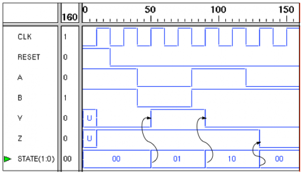
- No delay between STATE and output changes.
- “Spikes“ of original Mealy machine are gone!
Notes
The waveform shows the simulation results of the second version of the clocked Mealy automaton.
The output values change synchronously with the state changes now and undesired temporary values are eliminated.
Chapters of System Design > Synthesis > Finite State Machines and VHDL